IV Curve Tracing
IV Curve
The current-voltage (IV) curve is the most comprehensive single measurement available for a PV string or module. It reveals cell health, connection quality, shading impacts, and degradation modes that no other single test can expose. This section covers equipment selection, field methodology, data interpretation, and standards compliance for IV curve measurement across commissioning and O&M applications.
A Voc and Isc check confirms two points on the curve. The IV trace captures every point between them, including fill factor, Pmax, and the curve shape. Shape deviations — a sloped top, a rounded knee, or stepped current drops — identify specific fault types such as shunt resistance loss, elevated series resistance, or bypass diode activation that a two-point check will completely miss.
At commissioning to establish a Geff-corrected baseline, and then whenever Isc screening or performance data flags a string as underperforming. Full IV campaigns are also appropriate at warranty milestone intervals — typically Year 1 and Year 5 — to document degradation against nameplate. Routine O&M relies on faster Isc screening first, with IV tracing used to characterise flagged strings.
IEC 61829 recommends a minimum of 700 W/m² for commissioning-grade IV measurements. Below this level, measurement uncertainty increases and STC correction becomes less reliable. Clear-sky conditions between 09:00 and 15:00 solar time are ideal. Irradiance should be stable within ±2% over the measurement period to avoid sweep-to-sweep variation.
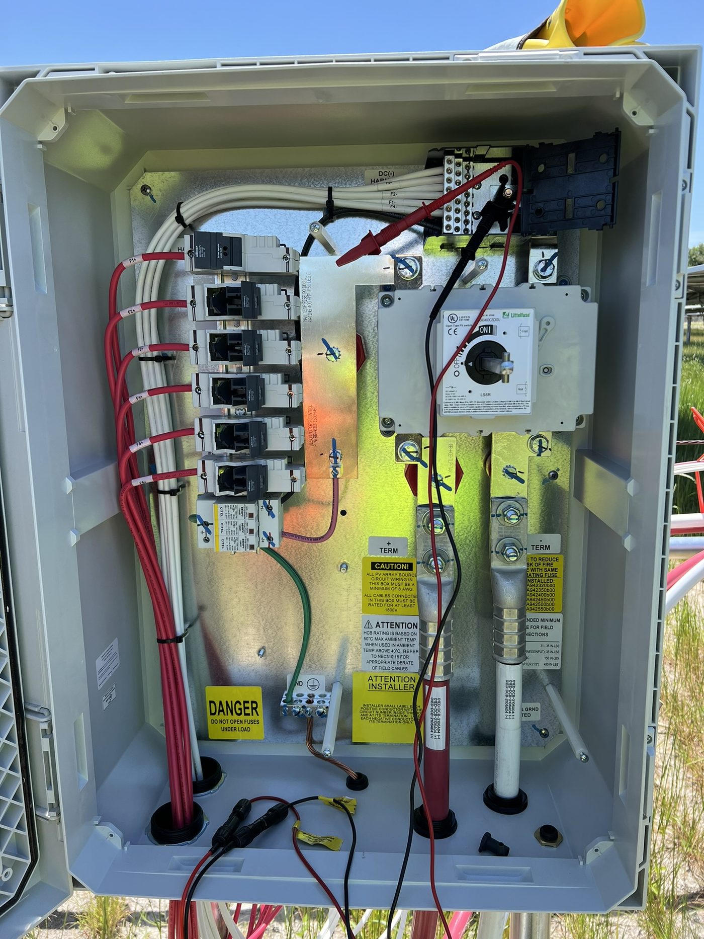
No. IV curve tracing requires the string to be isolated from the inverter at the DC disconnect or combiner. The tracer sweeps the string from short-circuit to open-circuit, which is incompatible with an inverter actively controlling the operating point. Always isolate the string, verify zero voltage at the tracer terminals before connecting leads, and follow lockout/tagout procedures.
The most common cause is using front-side irradiance alone for correction on bifacial module strings, without accounting for rear-side contribution via the Geff calculation. This understates the actual irradiance the module received, so the correction overshoots. Other causes include sensor misalignment, irradiance measurement taken at a different plane than the module, or genuine module outperformance within tolerance bins.