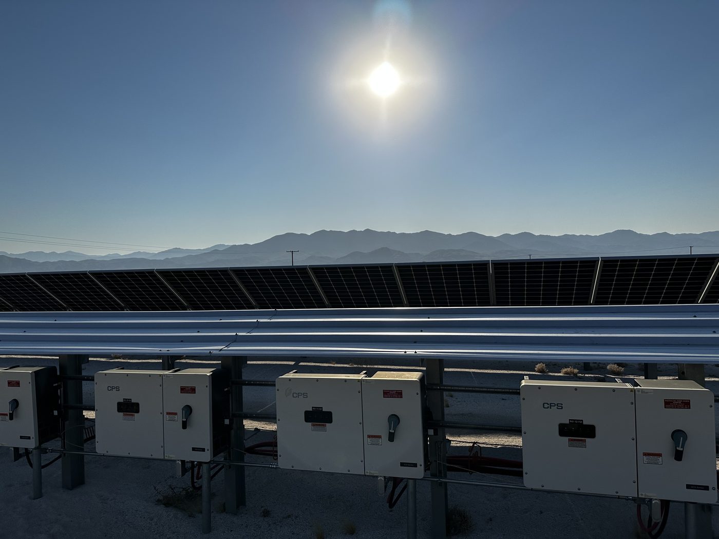
Bifacial Module Testing
Bifacial Modules
Bifacial modules generate power from both front and rear surfaces, introducing new measurement challenges that standard monofacial test protocols were not designed to address. Rear-side irradiance varies with albedo, mounting height, row spacing, and tracker angle — all of which affect output in ways that a single reference cell cannot capture. This section covers bifaciality factor measurement, rear irradiance instrumentation, STC correction for bifacial devices, and field acceptance testing considerations.
Standard procedures correct field measurements to STC using front-side plane-of-array irradiance alone. Bifacial modules also generate power from rear-side reflected irradiance. Ignoring rear irradiance understates the total effective irradiance the module received during the test, causing the STC-corrected result to appear artificially inflated or to produce an incorrect commissioning baseline that cannot be reliably compared to future measurements.
Geff is effective irradiance — a single value that combines front-side and rear-side irradiance, weighted by the module's bifaciality coefficient, into one equivalent irradiance figure. It is the correct irradiance input for IEC 60891 STC correction of bifacial string measurements. Without Geff, your correction math is based on incomplete information about how much light the module was actually working with during the test.
Mount the rear-facing sensor coplanar with the module rear face at mid-module height. NREL field research shows rear irradiance non-uniformity of 30% or more between the lower module edge and module centre due to near-ground shading effects. A sensor placed at the lower edge significantly underreads average rear irradiance. Mid-height placement gives a reading representative of the module's full rear surface.
The bifaciality coefficient is published on the module datasheet and is measured per IEC TS 60904-1-2. It is typically listed as φPmax (for IV curve and power correction) and φIsc (for short-circuit current correction). Most commercial bifacial modules have coefficients between 0.65 and 0.80. If your datasheet does not list it separately, contact the module manufacturer for the IEC TS 60904-1-2 test report.
Always test mid-array, mid-row strings for baseline documentation. End-of-row and array-edge strings receive unobstructed ground reflection from at least one side, giving higher rear irradiance than interior strings. Using edge strings to establish a commissioning baseline sets a standard that mid-array strings cannot meet under the same conditions, making future performance comparisons unreliable.